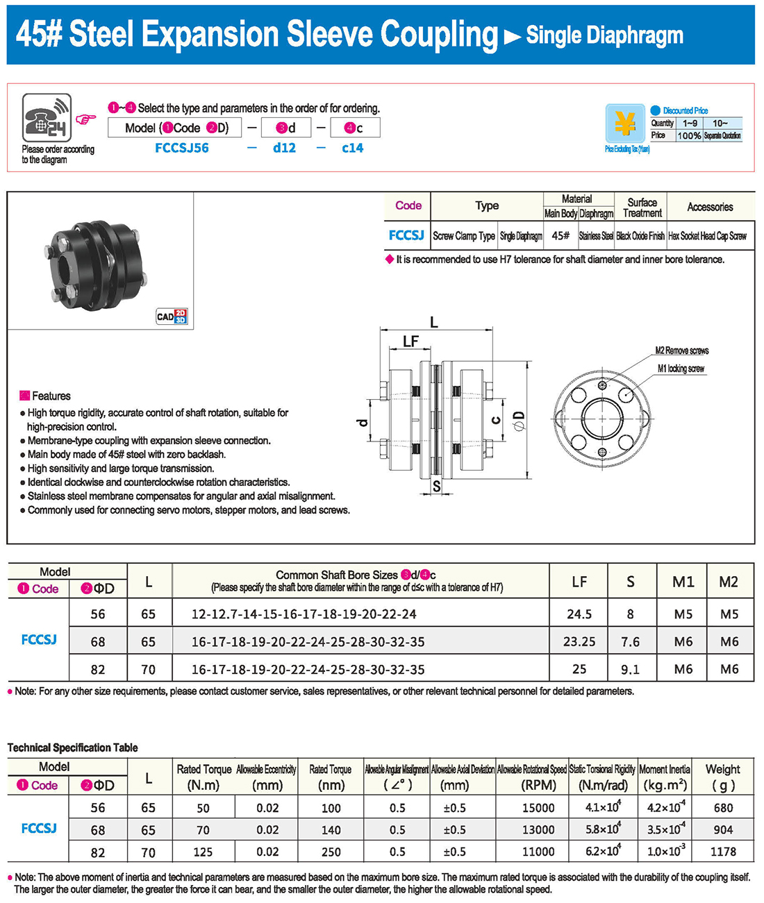
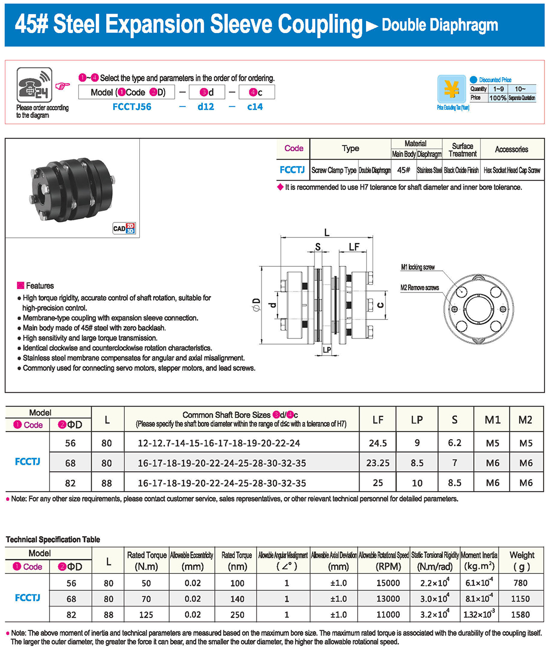
-
-
Коробка передач под прямым углом 90 градусов
- Aatm-как точное рулевое устройство серии
- Точное рулевое устройство серии AAT-AS
- Точность серии 90 градусов
- Pt-стандартное рулевое устройство серии
- Серия точных 90 - градусного редуктора
- На входном рулевом устройстве оси серии
- Фланцевый вход серии AT-F 90 - градусный редуктор
- Синхронный винтовой лифт серии RB
- Классический планетарный вклад кно в управление
- CCT классический вход в шахту руля
-
-
-
-
- Руль для рук
- - с ручкой
- Различные типы ручек
- Штырь/штырь
- В центре города
- Категория защиты от ударной абсорбции
- Пневматические зажимы/быстрые зажимы
- Размещение деталей/направляющих частей
- Фиксатор/фиксатор позиционирования
- Мелкие детали/магнит
- Монтажные опоры/основания/крепления
- Соединительный блок
- Пневматические аксессуары и аксессуары
- Выравнивание ступней ног
- 3. Дверные замки
- Потяни за ручку.
- - петель
-
На электродвигателе
- Электродвигатель с открытым контуром + электродвигатель с закрытым контуром + винтовой шаговый электродвигатель
- Водитель автомобиля степпер (открытая/закрытая петля)
- Серводвигатель переменного тока + водитель серводвигателя переменного тока
- Серводвигатель постоянного тока + водитель серводвигателя постоянного тока (импульсный + тип шины)
- Двигатель постоянного тока без щетки и драйвер постоянного тока без щетки
- Прямой привод DD motor + линейный двигатель
- ПЛК программируемый контроллер/контроллер движения (карточная/визуальная система управления все в одном устройстве)
- Взрывозащищенный специальный двигатель


 Английский язык
 Русский язык
 На испанском языке
 На итальянском языке
 Арабский язык
 Корейская народно-демократическая республика
 Немецкий язык
 На японском языке
 На вьетнамском языке
 На турецком языке
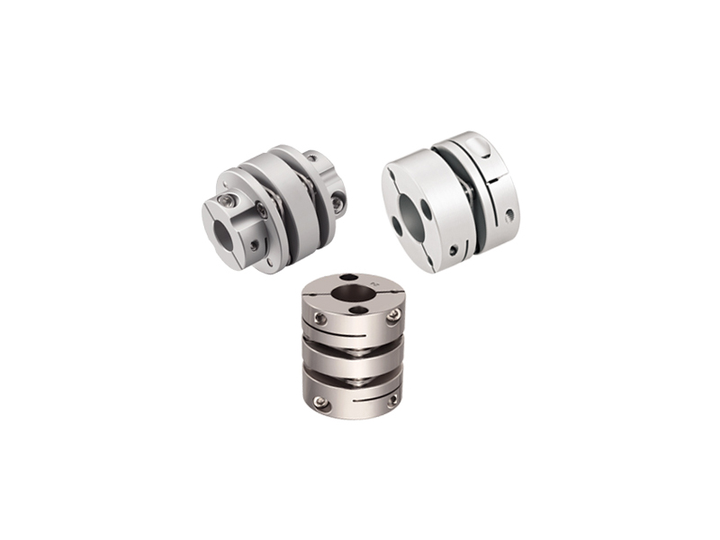
 1. Введение
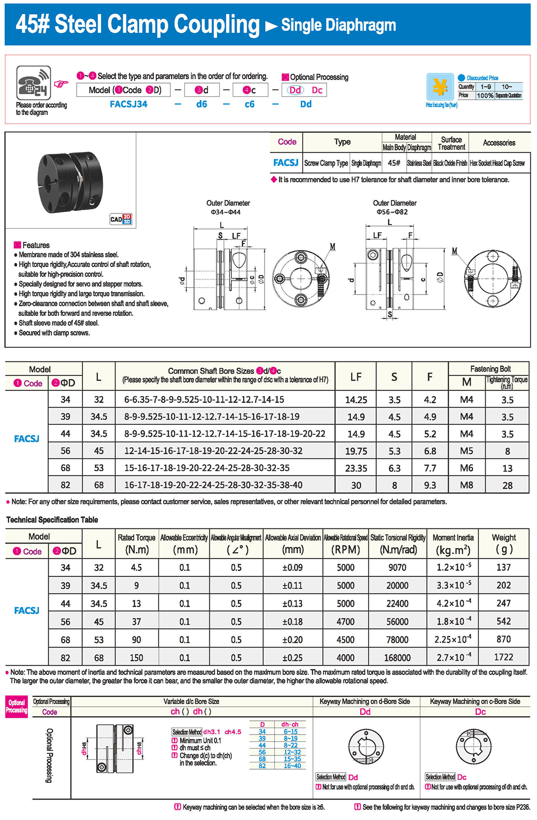
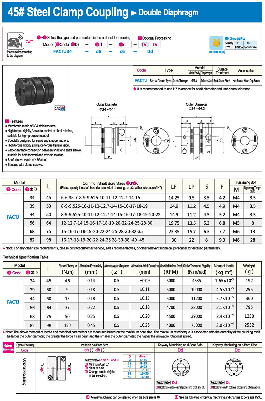
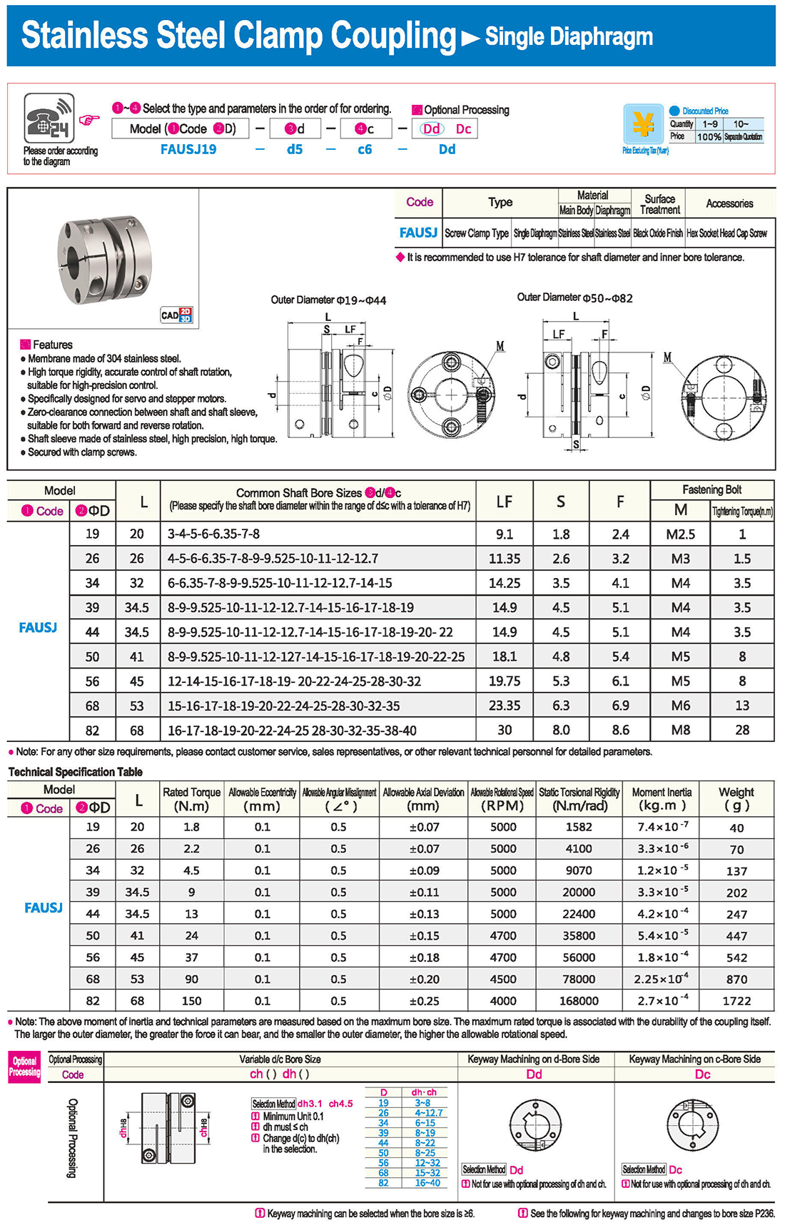
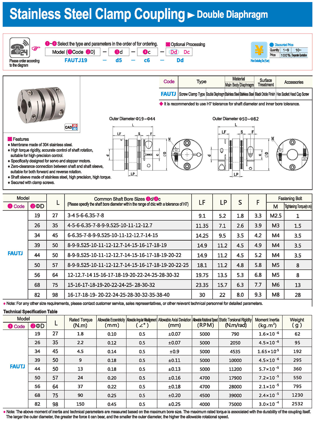
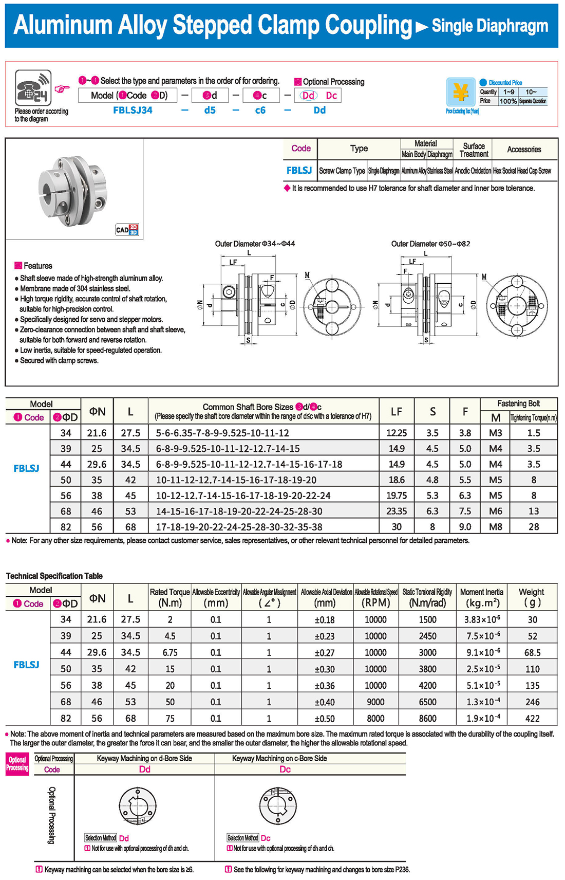
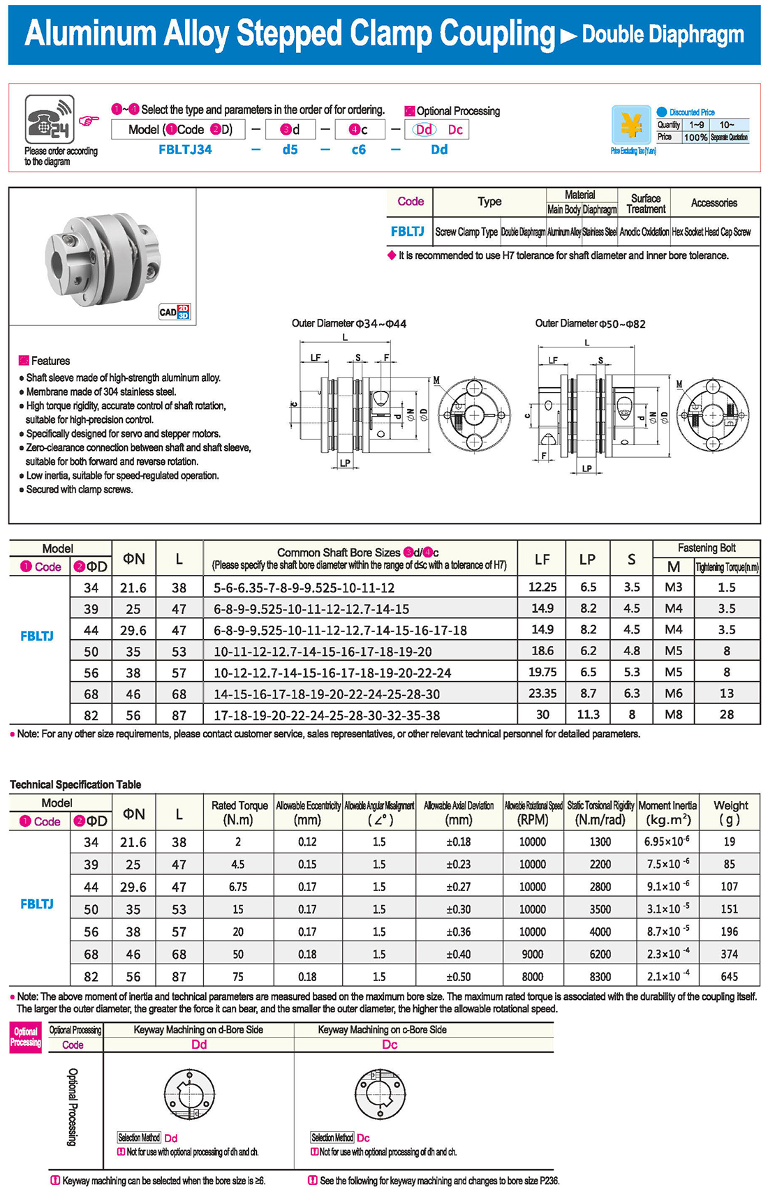
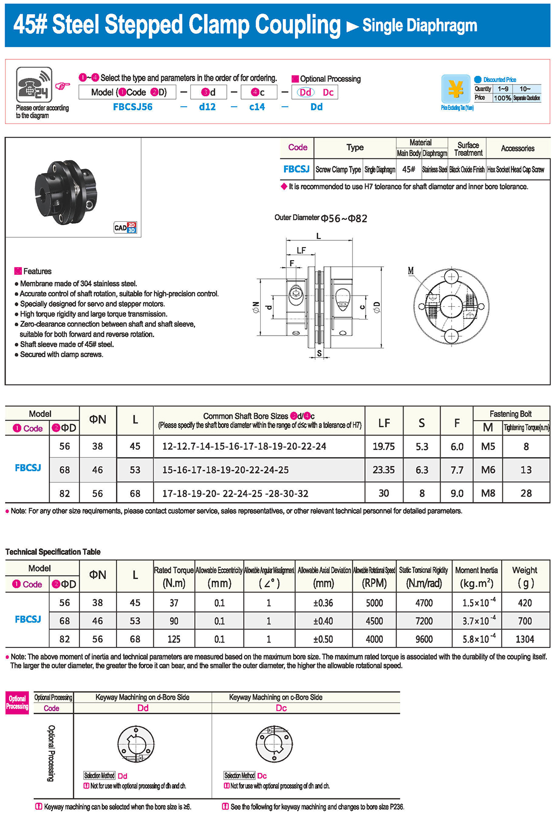
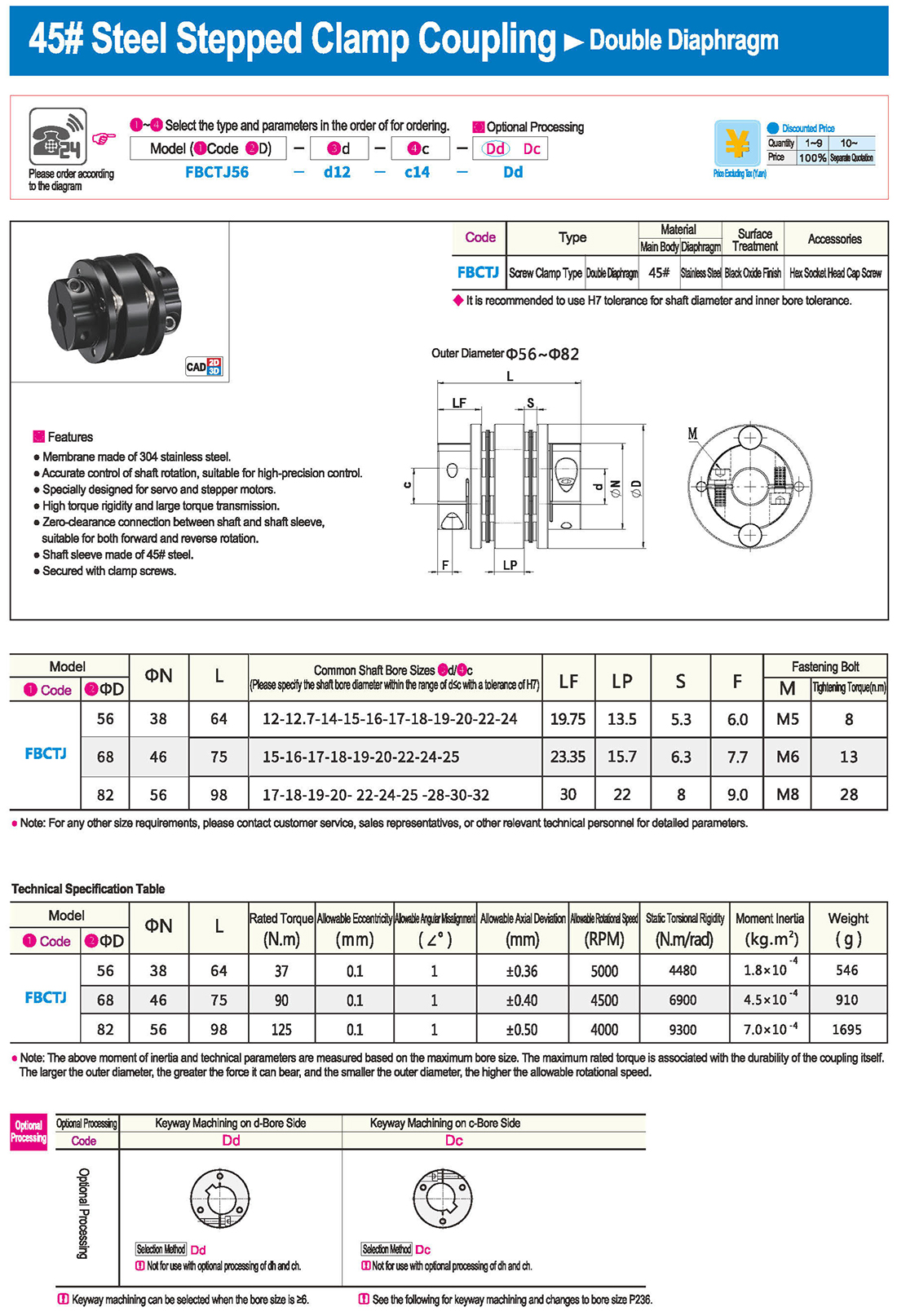
 Таблица технических характеристик
 скачать