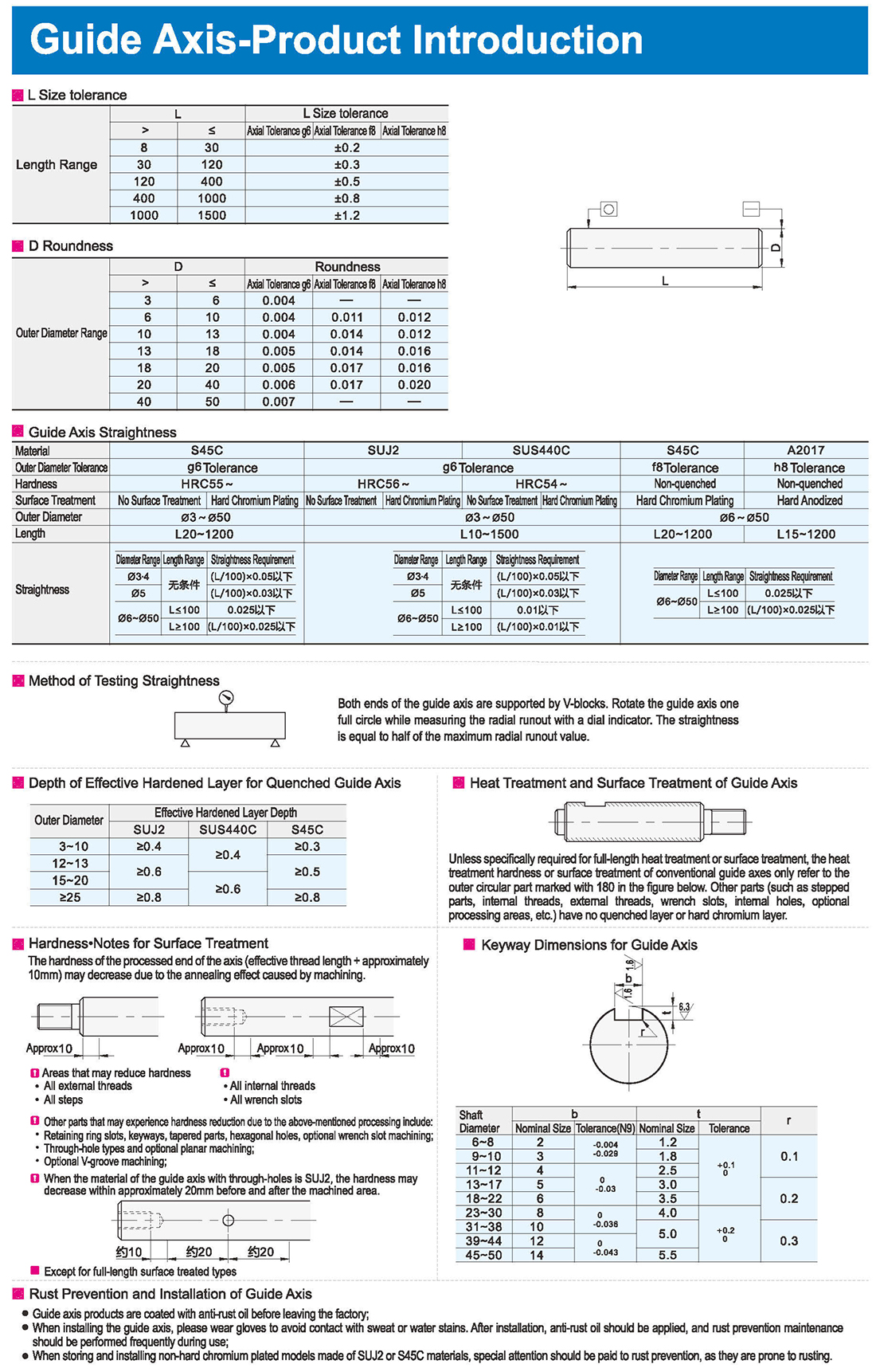
1. Глубина эффективного затвердевшего слоя для затухающей направляющей оси
2. Тепловая обработка и поверхностная обработка направляющей оси.
За исключением случаев, когда это конкретно требуется для полной или поверхностной термической обработки, твердость или поверхностная обработка обычных направляющих осей относятся только к наружной круглой части, обозначенной на рис. 180 ниже. Другие части (такие, как ступенчатые части, внутренние нити, внешние нити, гаечные щели, внутренние отверстия, дополнительные зоны обработки и т.д.) не имеют потухшего слоя или твердого хрома.
3. Предотвращение ржавчины и установка направляющей оси
Продукция направляющей оси покрыта противоржавым маслом перед уходом с завода;
При установке направляющей оси, пожалуйста, носите перчатки, чтобы избежать контакта с пятнами пота или воды. После установки следует применять противоржавое масло, а во время эксплуатации следует часто проводить техническое обслуживание в целях предотвращения ржавчины;
При хранении и установке нетвердых хромированных моделей, изготовленных из материалов SUJ2 или S45C, особое внимание следует уделять предотвращению ржавчивости, поскольку они подвержены ржавчивости.
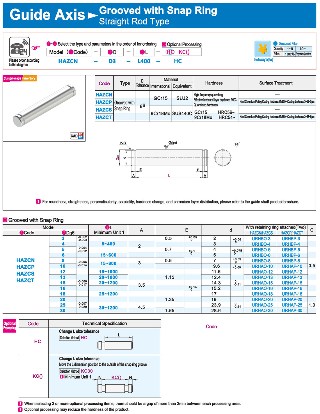
1.Grooved with Snap Ring
Cancel snap ring groove on one end Move the L dimension position to the outside of the snap ring groove
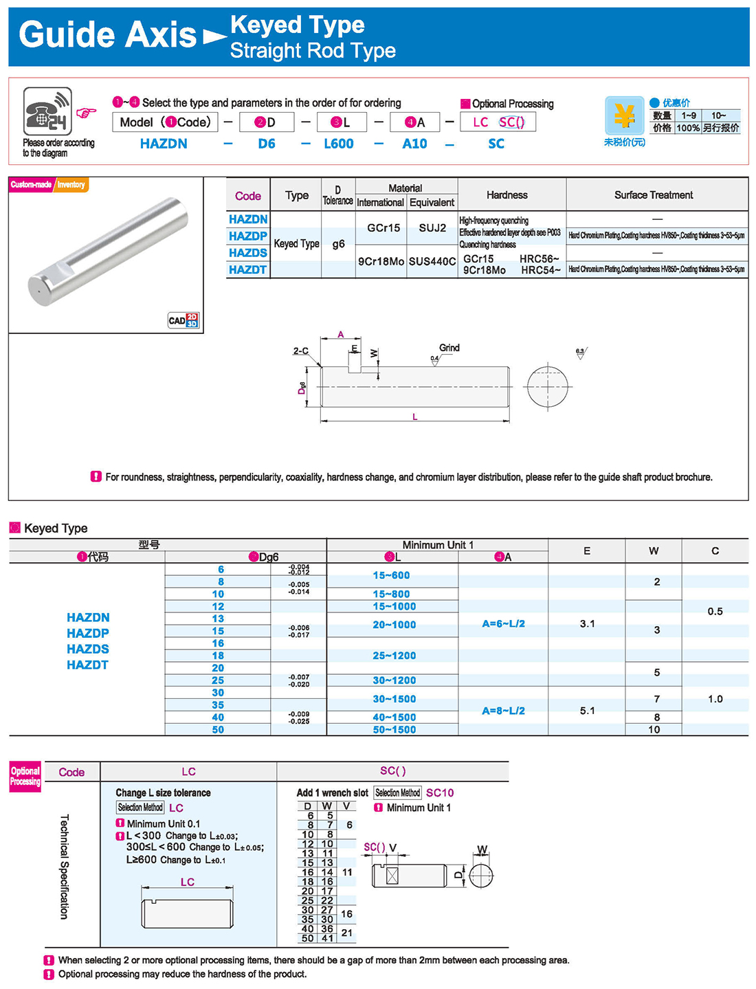
2.Keyed Type Internal Thread on One End
Precision Grade Ordinary Grade Precision Grade
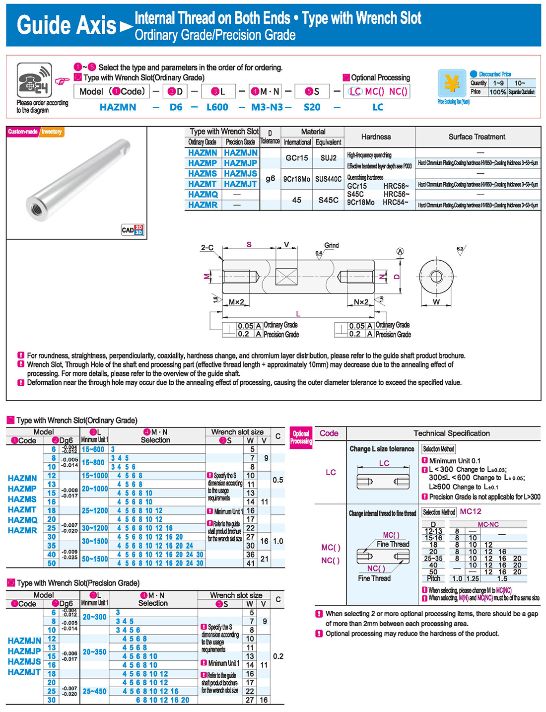
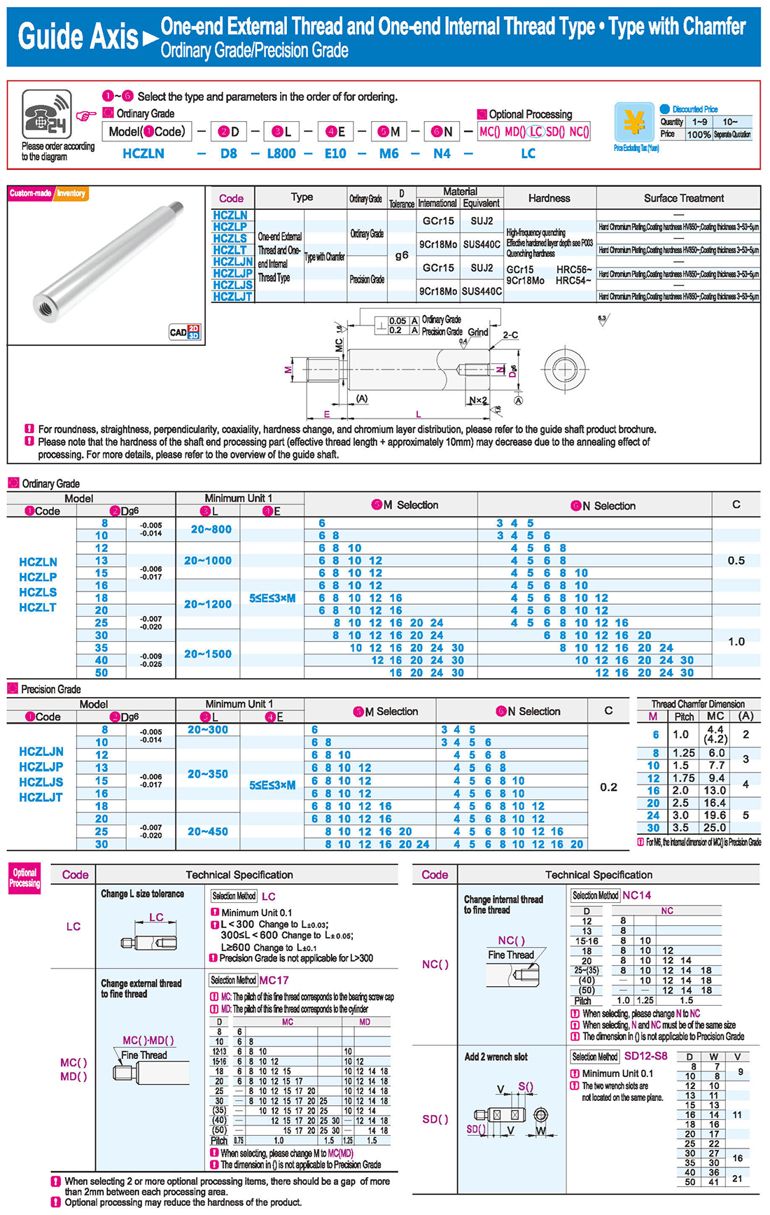
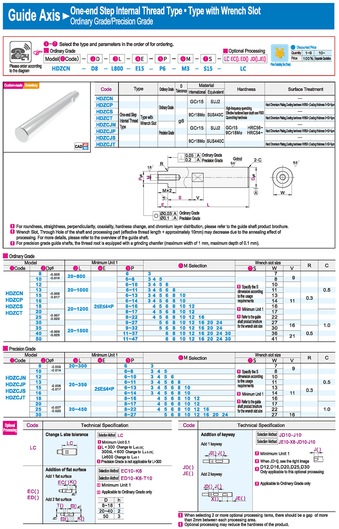
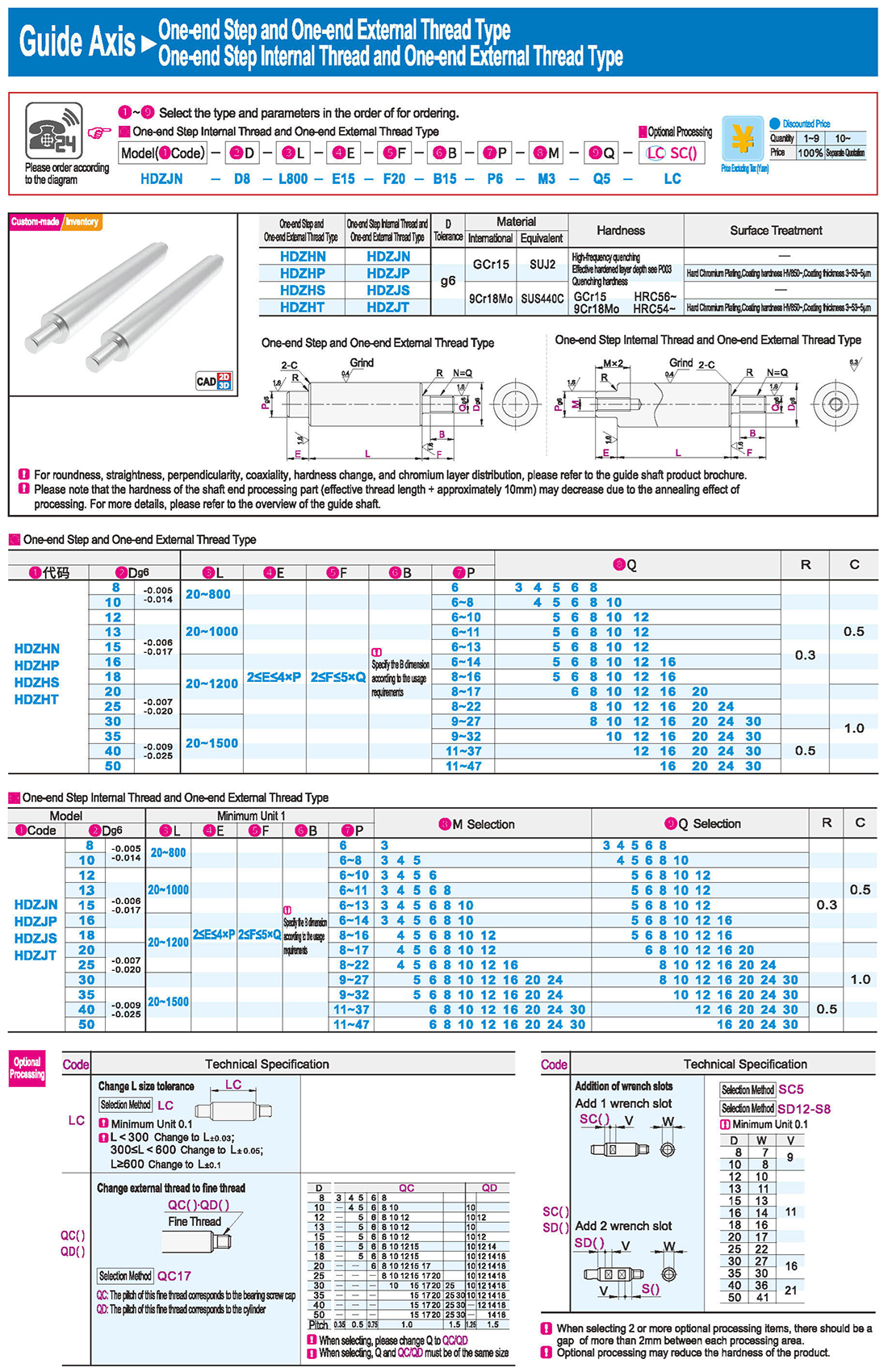
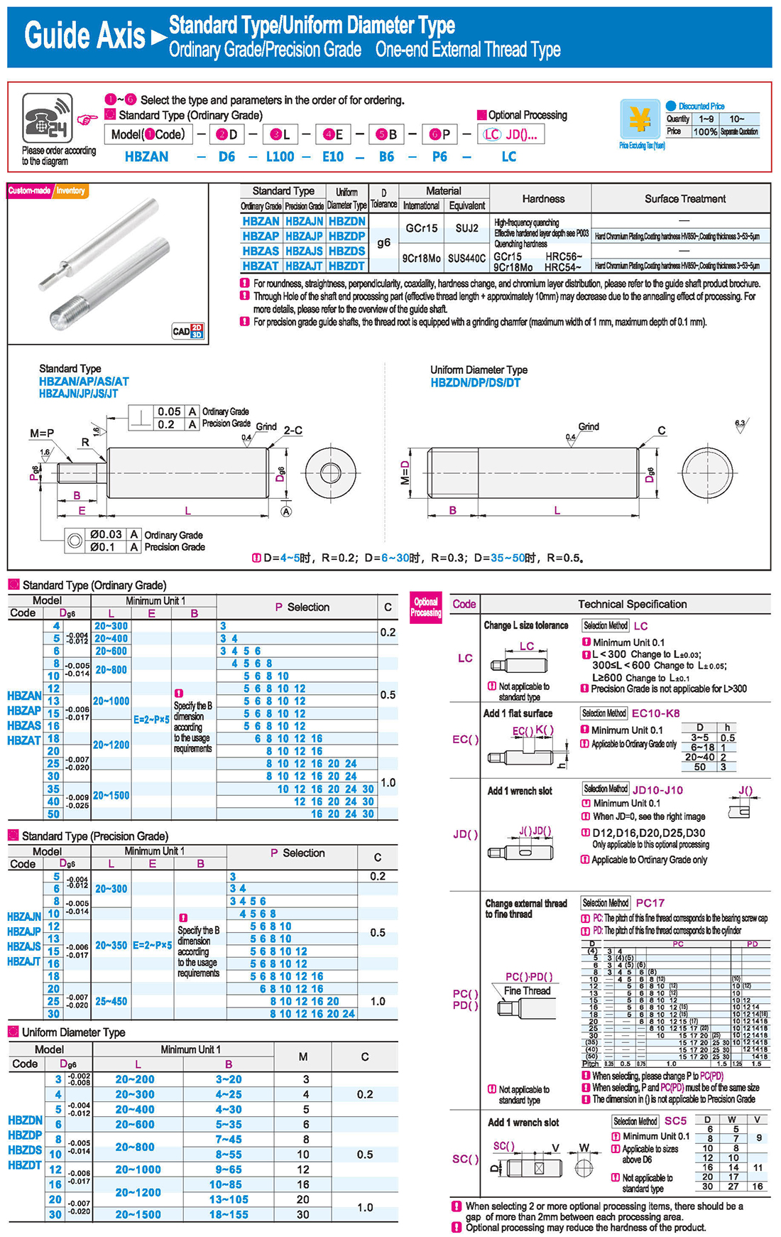
Please note that the hardness of the shaft end processing part (effective thread length + approximately 10mm) may decrease due to the annealing effect of processing. For more details, please refer to the overview of the guide shaft.
Selection: Precision Grade is not applicable for L>300
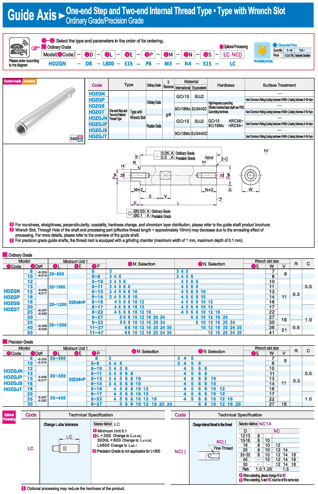
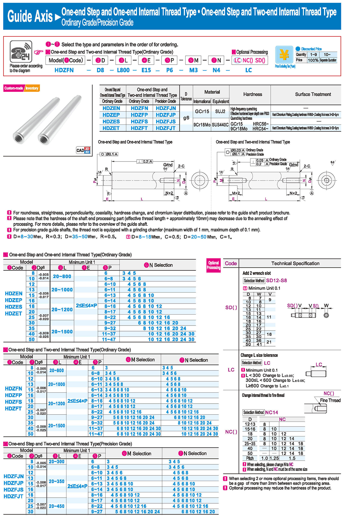
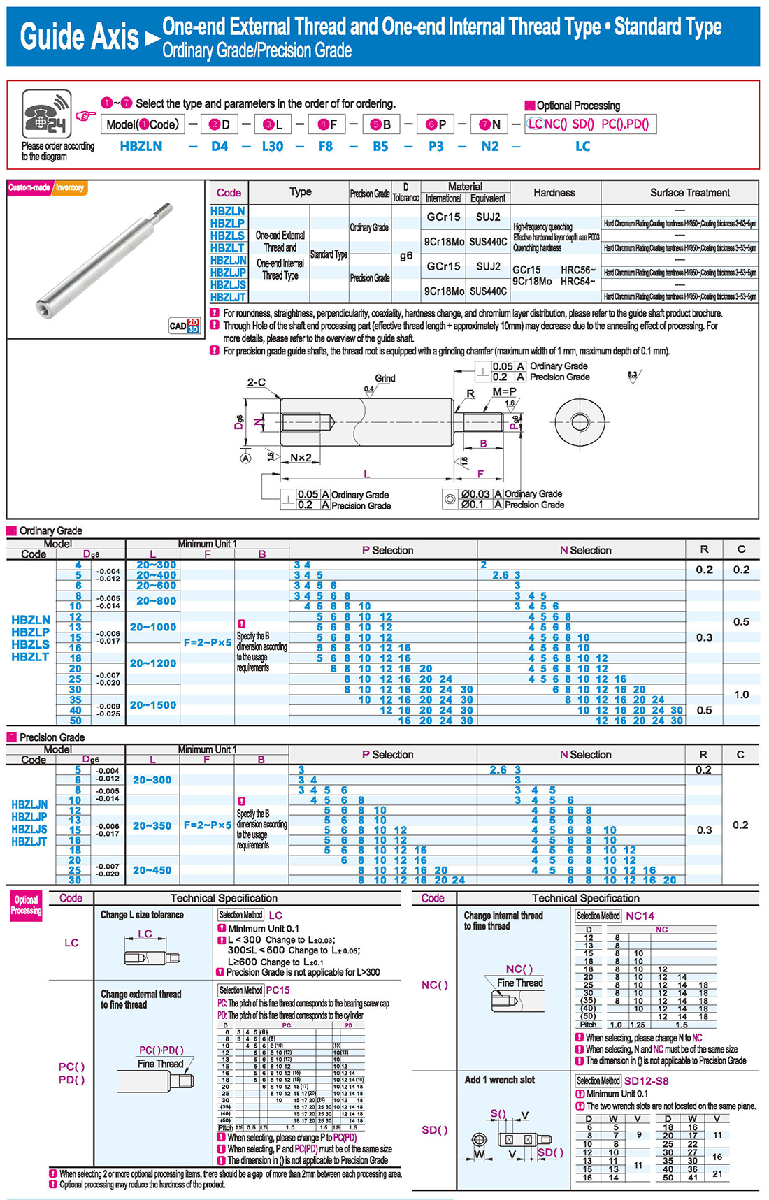
Change internal thread to fine thread Pitch Fine Thread
When selecting, please change M to MC
M and MC must be of the same size
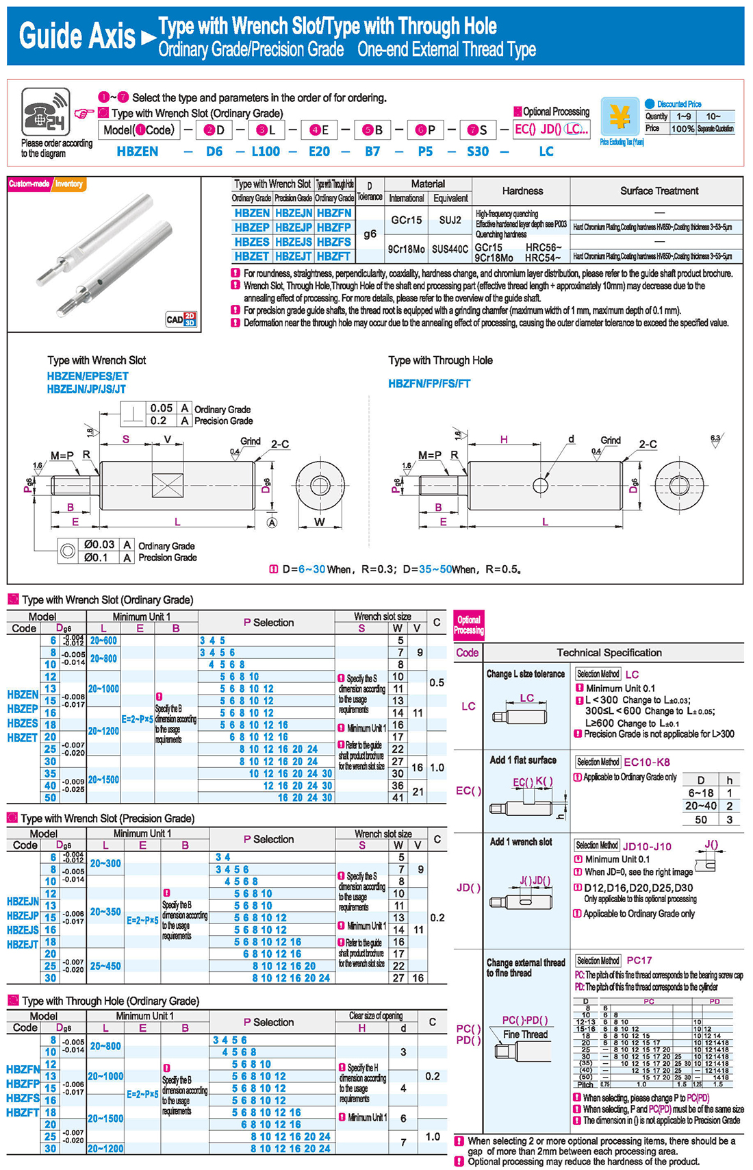
Applicable to Ordinary Grade only
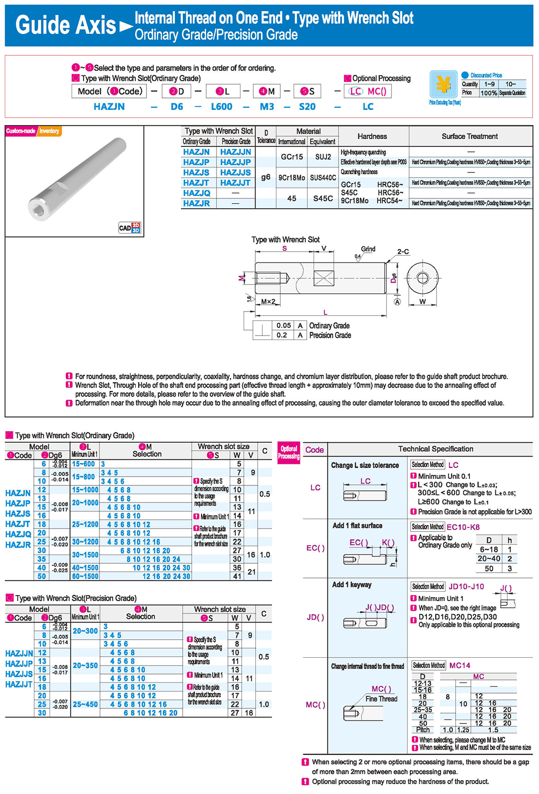
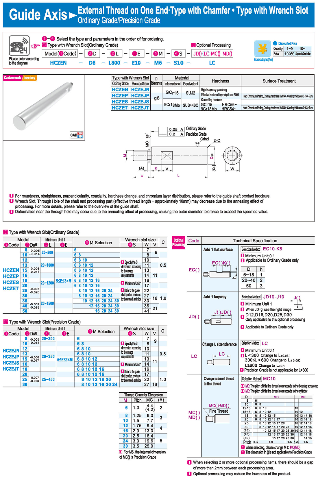
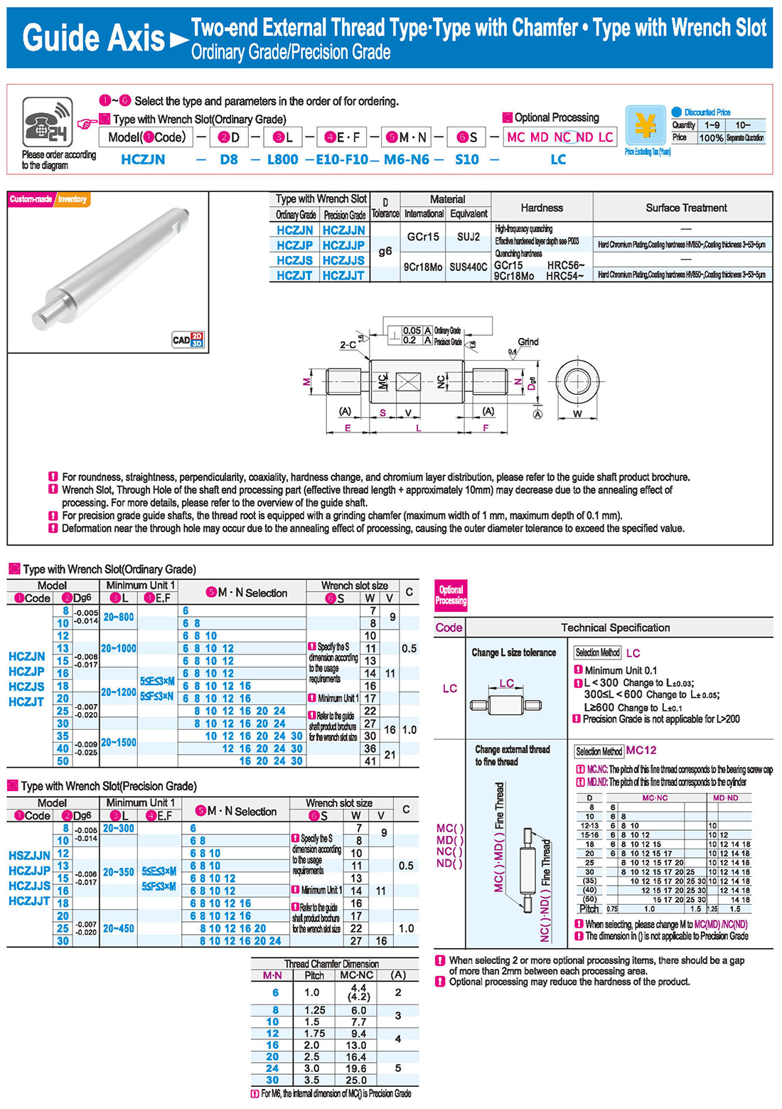
3.Type with Wrench Slot
Deformation near the through hole may occur due to the annealing effect of processing, causing the outer diameter tolerance to exceed the specified value.
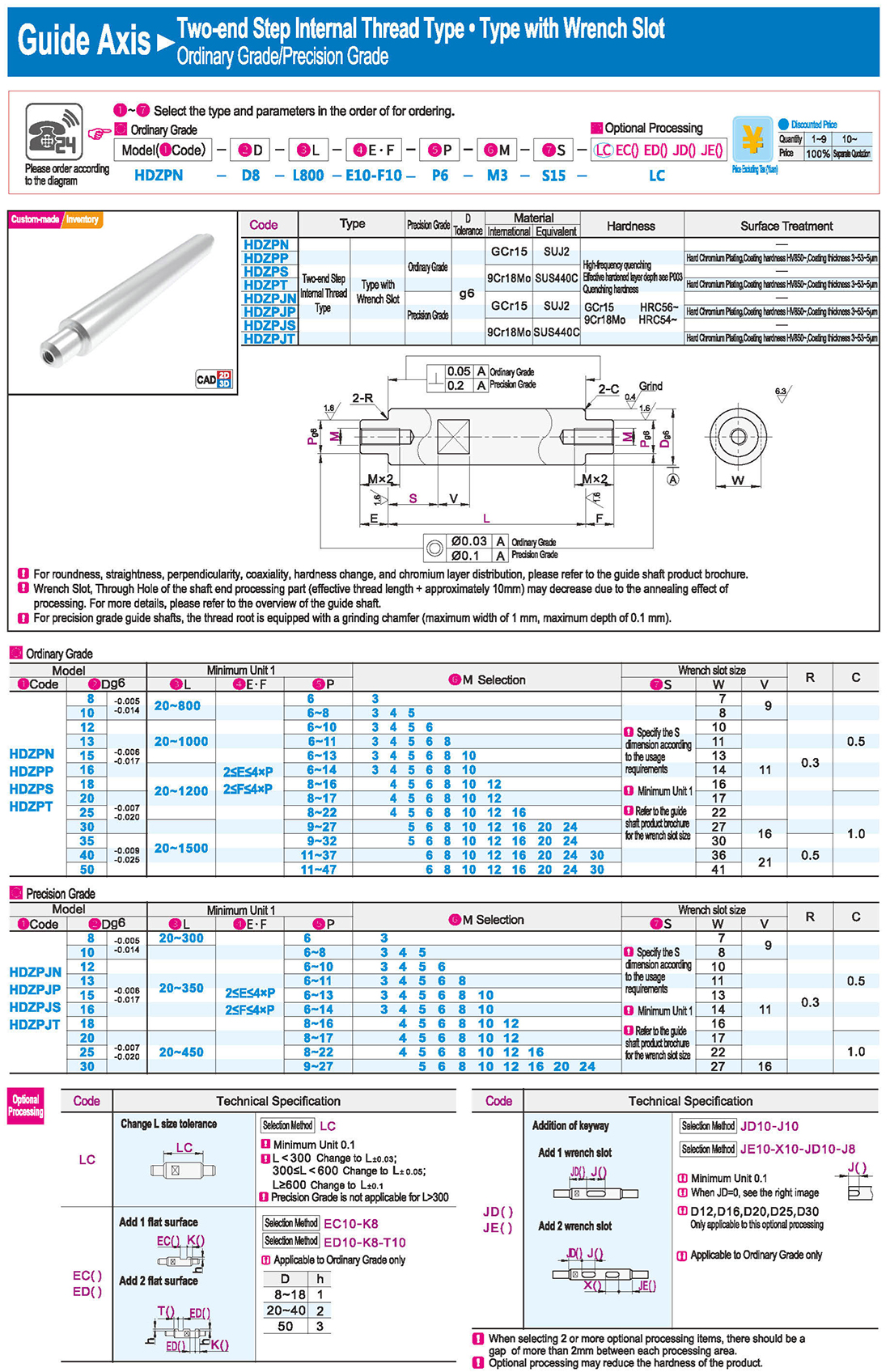
Specify the S dimension according to the usage requirements
Refer to the guide shaft product brochure for the wrench slot size
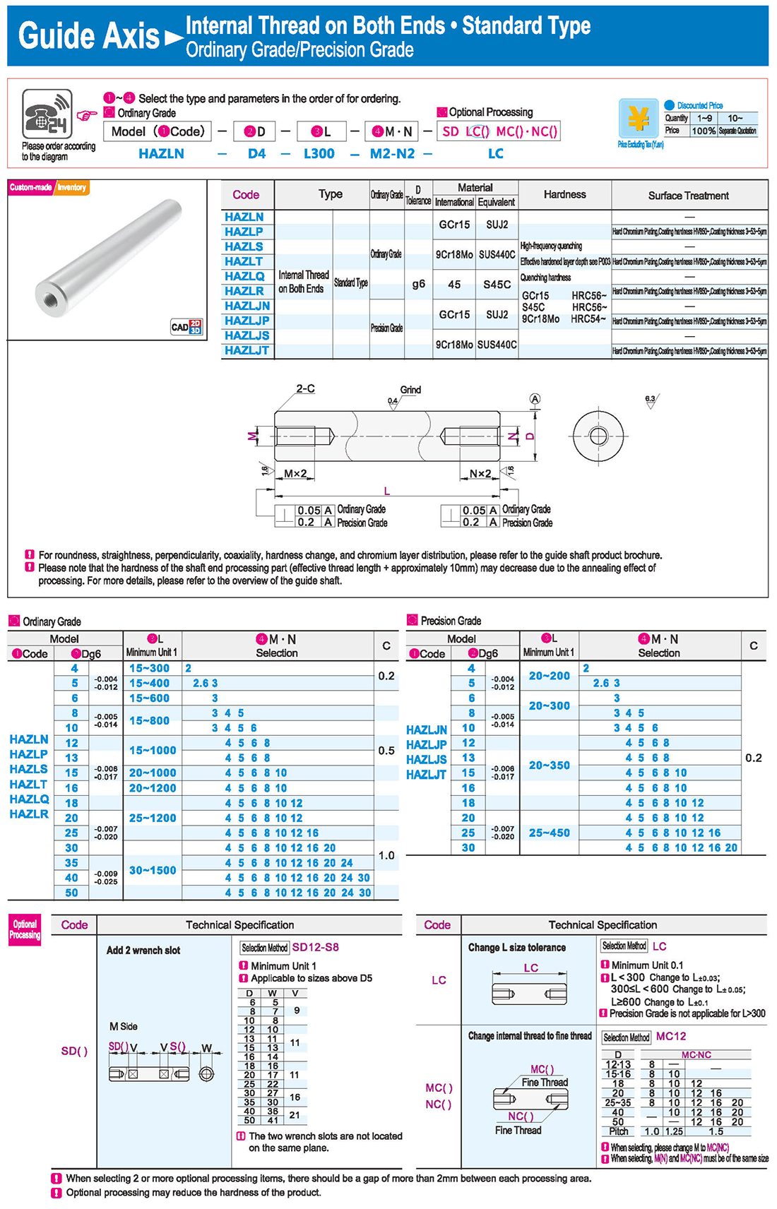
4.Internal Thread on Both Ends
The two wrench slots are not located on the same plane.
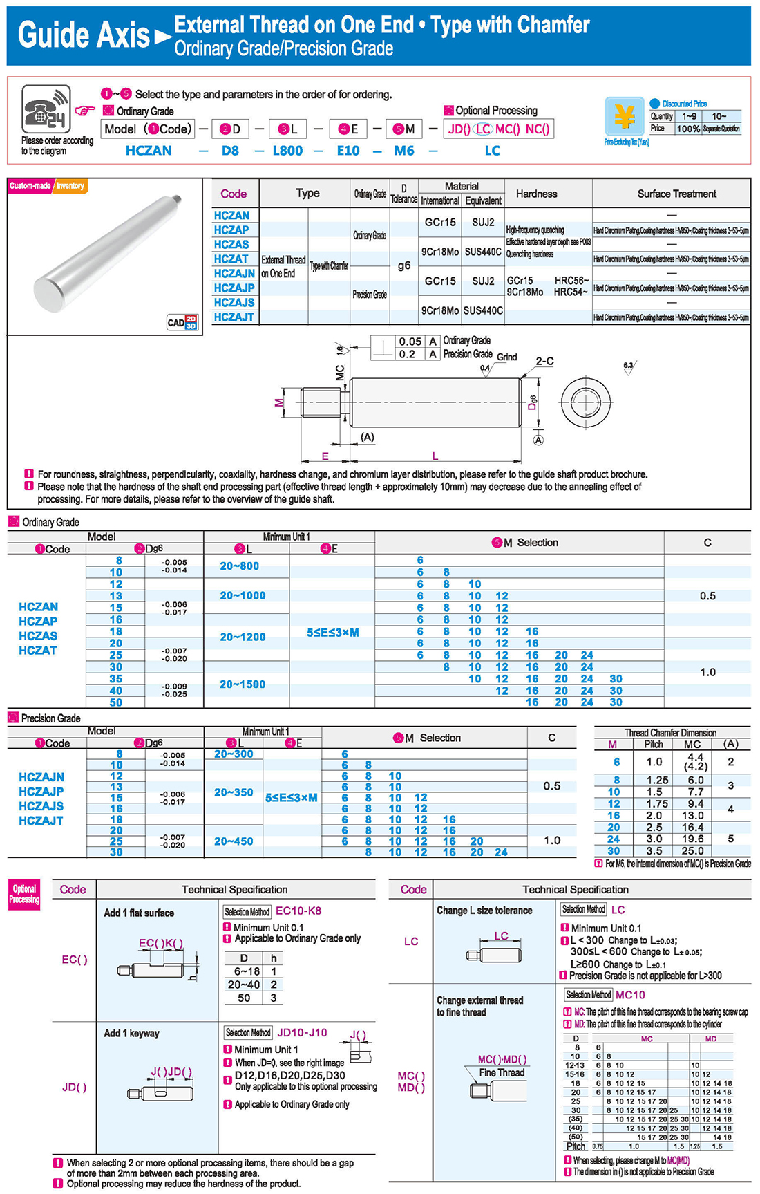
5.External Thread on One End · Type with Chamfer
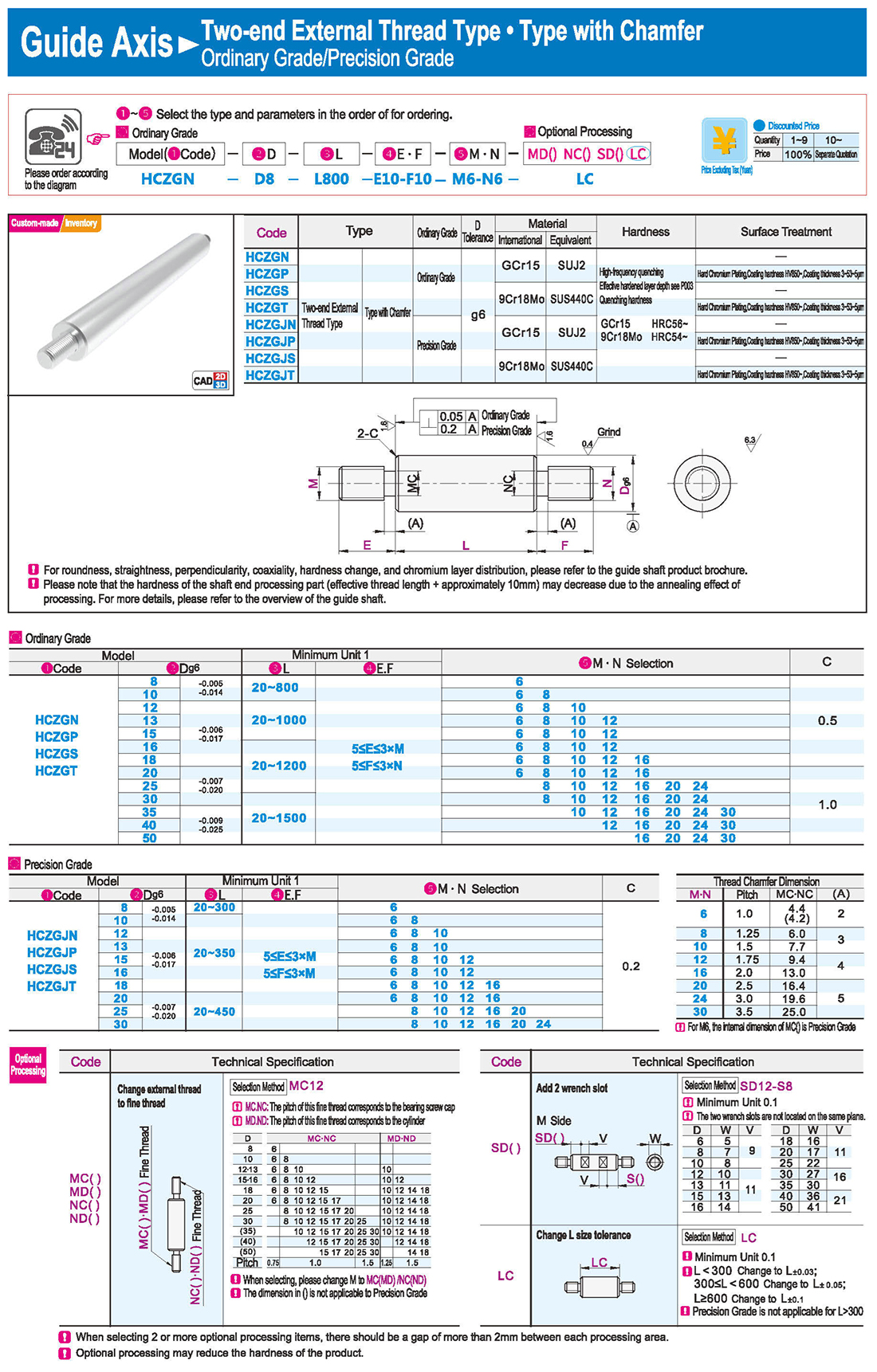
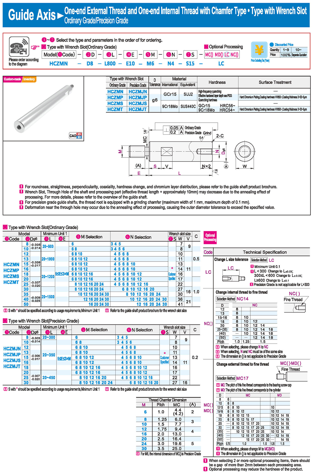
Thread Chamfer Dimension
For M6, the internal dimension of MC() is Precision Grade
MC: The pitch of this fine thread corresponds to the bearing screw cap
MD: The pitch of this fine thread corresponds to the cylinder
The dimension in () is not applicable to Precision Grade
6.One-end External Thread and One-end Internal Thread with Chamfer Type
Customer Specified
S with * should be specified according to usage requirements
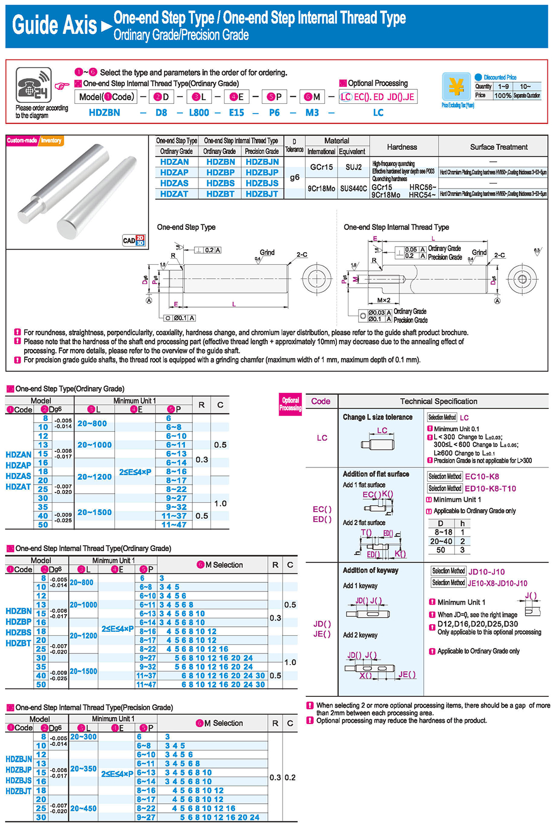
7.One-end Step Type / One-end Step Internal Thread Type
One-end Step Type / One-end Step Internal Thread Type
One-end Step and One-end Internal Thread Type · One-end Step and Two-end Internal Thread Type
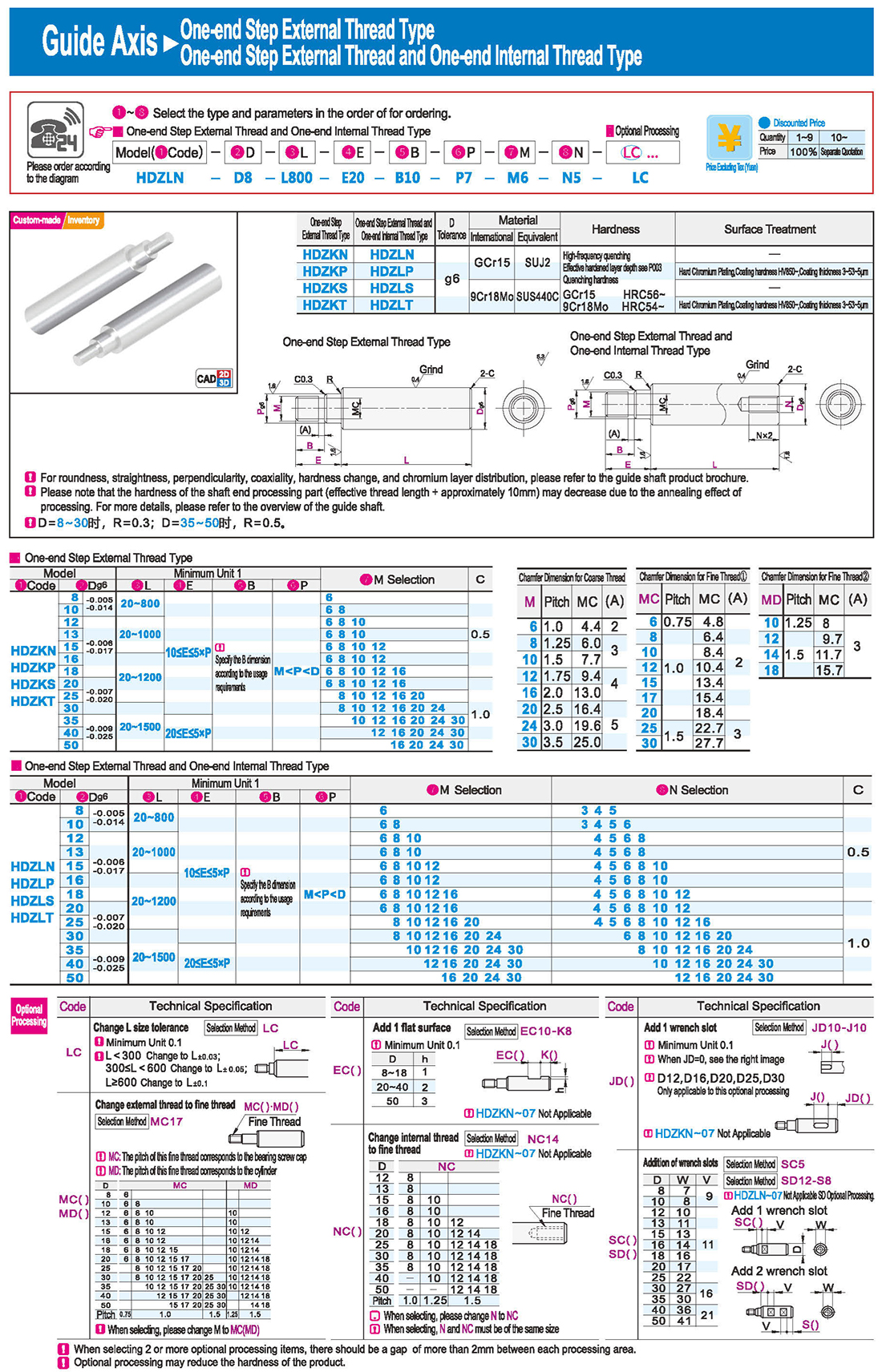
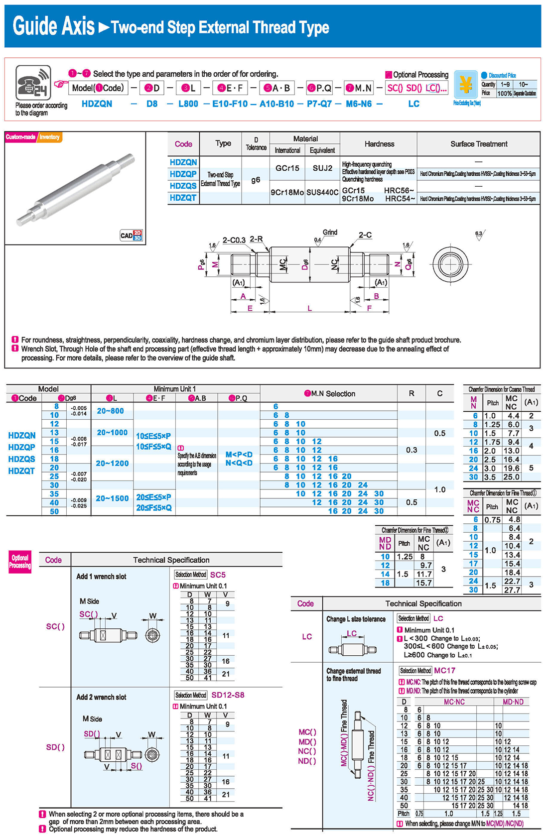
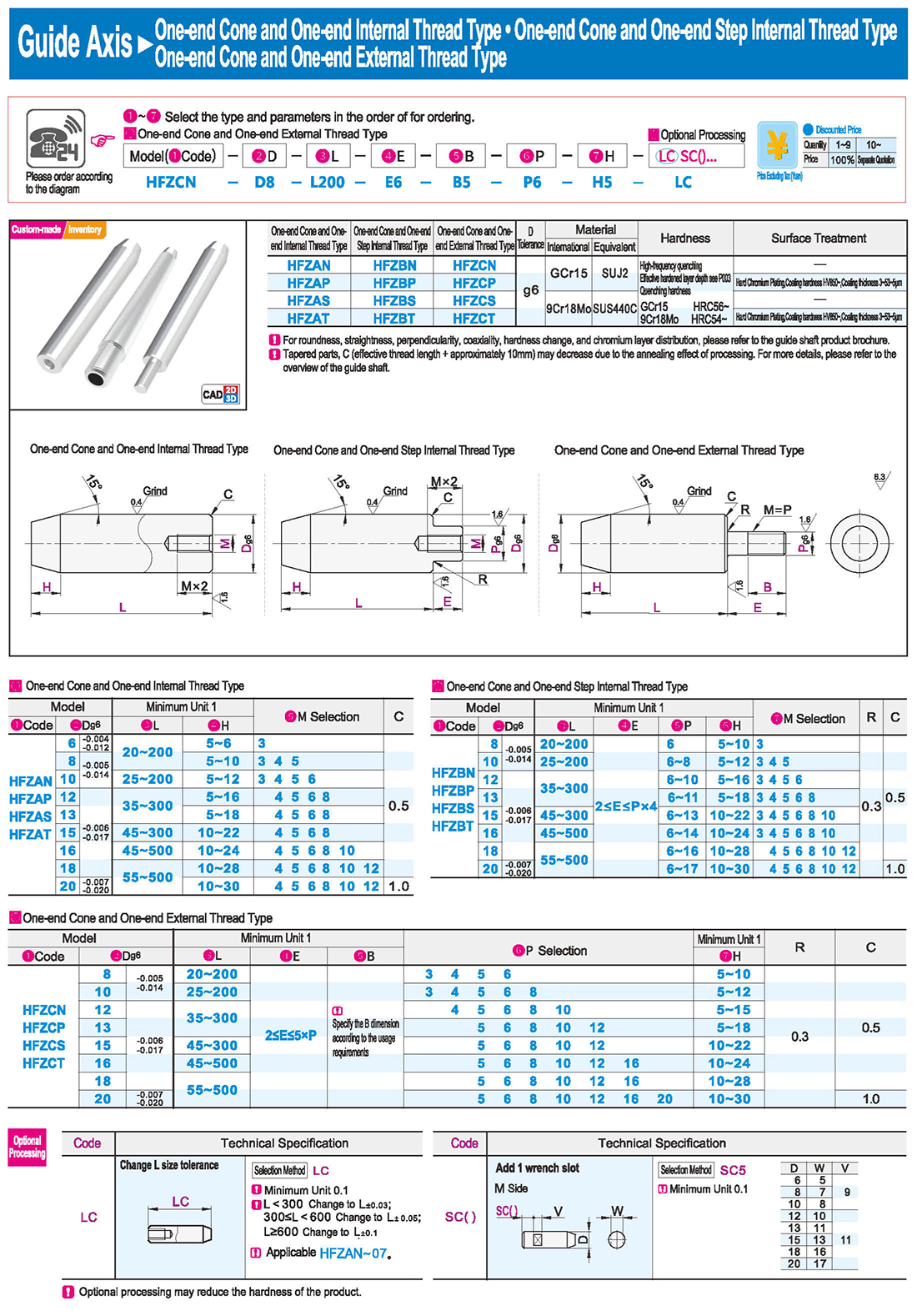
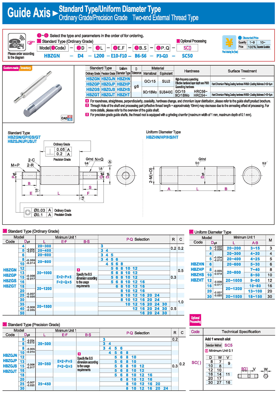
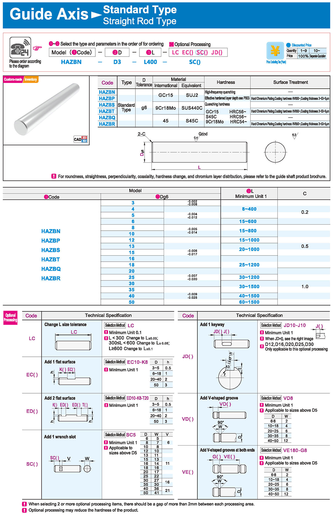
Optional processing may reduce the hardness of the product
One-end Step and One-end External Thread Type
One-end Step Internal Thread and One-end External Thread Type
Change external thread to fine thread
One-end Step External Thread Type
One-end Step External Thread and One-end Internal Thread Type
Chamfer Dimension for Coarse Thread
Chamfer Dimension for Fine Thread
Two-end Step Type · Two-end Step Internal Thread Type
Two-end Step External Thread Type
One-end Cone and One-end Internal Thread Type · One-end Cone and One-end Step Internal Thread Type
One-end Cone and One-end External Thread Type
Uniform Diameter Type
Ordinary Grade/Precision Grade One-end External Thread Type
Type with Through Hole
One-end External Thread and One-end Internal Thread Type





 Английский язык
 Русский язык
 На испанском языке
 На итальянском языке
 Арабский язык
 Корейская народно-демократическая республика
 Немецкий язык
 На японском языке
 На вьетнамском языке
 На турецком языке
 1. Введение
 Таблица технических характеристик
 скачать


